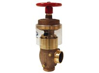
Image for Illustration purposes only. Actual product may vary
Dixon
FAPRAVG250G Field Adjustable Pressure Reducing Angle Valve
MODEL FAPRAVG250G
Contact supplier for technical support on: 8779634966
$1,032.96 Each
Prices are subject to change
FREE SHIPPING ON ORDERS OVER $1
Select Quantity
 Free Gift with this product
Typically Ships in: 1 day
Returnable: See conditions
Still Deciding?
Add this item to your saved items and easily come back later.
Material
Cast brass
Inlet
2-1/2 in grooved
Outlet
2-1/2 in grooved
Applications
Used in applications where the inlet pressure is greater than 175 PSI
Available Options
Tamper switch available, contact Dixon for details.
Construction
- 1/4" NPT gauge ports - both sides
- Drilled and tapped standard
Features
- Gives the contractor flexibility during installation, and the ability to adjust the settings once installed, as hydraulic conditions change.
- 3/8" adjusting rod included
Installation
- Standpipe Systems: For valves intended for use in a Class II standpipe system, use a straight stream nozzle with a 1/2" orifice or a 1-1/2" combination fog/straight stream nozzle. Nozzles shall have a rated flow range compatible with the performance characteristics of the pressure-reducing valve. Valves shall be installed in accordance with NFPA 14 and/or 13 and NFPA 25 and shall have a minimum outlet pressure of 65 PSI. They valve may be set for residual pressures less than 100 PSI when permitted by the authority having jurisdiction. Upon system completion, each valve must be tested under both flow and no-flow conditions to verify outlet pressure rates satisfy system design requirements in accordance with NFPA14.
- Automatic Sprinkler Systems: Automatic sprinkler systems are used to reduce the water supply pressure at which the sprinklers are designed to operate and may be used as a floor control valve suitable for indicating service and also as a checking device. Valves shall be installed in accordance with NFPA 13 and 25. A relief valve of not less than 1/2" shall be installed on the downstream side of the pressure reducing or pressure control valve and pressure gauges shall be installed on the upstream and downstream sides of the valve. Upon system completion, each valve must be tested under both flow and no-flow conditions to verify outlet pressure rates satisfy system design requirements in accordance with NFPA13.
- Valve Maintenance: Visual inspection of the valve body, threads, and cover should be conducted prior to installation and periodically to insure there is no physical damage. Valves are designed so the stem packing may be replaced without removing the valve from the piping system. The valve must be in the fully open position; remove handwheel and packing nut, replace stem packing o-ring. Visual inspection is recommended to assure no damage to the valve body, threads or handwheel. Replacement of internal parts is not recommended. The valve must be installed with pipe unions or rubber gasketed fittings upstream or downstream of the valve to permit easy removal for replacement. The valve should be tested and maintained in accordance with NFPA 25.
Safety Notes
- Failure to follow installation and operating instructions could result in serious and disabling injury or death to the user or others or destructive damage to property. Never use or operate this valve without inspecting it for safe and appropriate operation.
- The valve selected must not exceed 175 PSI output either static or residual, nor can the inlet residual pressure exceed 400 PSI.
- Inlet pressures as high as 400 PSI are permitted on settings 1 and 5. Inlet pressure setting 10 should not exceed 350 PSI. Inlet pressure on setting 15 should not exceed 250 PSI.
- Pressure can be expected to increase 20-25 PSI for each major division of the setting and to drop an average of 4 PSI per 50 GPM of flow.
- For the '10' and '15' settings, outlet pressure follows inlet pressure up to 100 PSI, until pressure in the piston chamber overcomes the spring.
- Do not use in sprinkler systems without outlet pressure below 50 PSI.
Specifications
UL Listed
Use
- Determine desired outlet pressure for known inlet pressure
- Remove the tamper-resistant screw and slide the plastic cover up to access the adjusting nut.
- Use a 3/8" diameter rod in any one of the 6 holes in the adjusting nut and rotate counter clockwise to increase the pressure at the outlet.
- Check valve under pressure under static and under the anticipated flowing conditions to ascertain that the setting produces the expected results.
SKU: 107691
Solid valve!
I use these valves as the trigger for some flame effects. They snap back quickly and don't wear out or pass center and leak like cheaper versions. Best bang for your buck!
Read moreSKU: 2933980
Dixon 8hf8-b 1" iso-b coupler 1" nptf brass 200025-8
Great price, fast delivery.
Read moreSKU: 115099
Reasonable and reasonably fast shipping
My order was processed very quickly even with the changes I made on my original order with friendly people at MRO
Read moreWhen you get to checkout, you’ll be able to select a free gift! Depending on the cart value, you’ll be shown relevant gifts your order qualifies for.
$500
MRO Hat
MRO Golf Balls
MRO Hi-Vis Vests
MRO Mug
$750
32oz Water Bottle
Throw Blanket
30 piece Hex Set
Telescopic Pick Up
$1,250
Golf Cooler
11-in-1 Screw Driver Set
Gorilla Grip Knee Pad
John Deere Oilskin Hat
$2,500
Igloo 1/2 Gallon Jug
Rechargable Headlamp
Larix Trucker Hat
$5,000
Igloo 10 Gallon Cooler
Igloo Party Bucket Cooler
Klein Tools Speaker
Klein Tools 8-in-1
$7,500
GX-6F Pro Golf Range Finder
Bushnell Outdoorsman Speaker
Jaeger 24px Ratcheting Wrench Set
Aspen Beverage Bucket