










We never sell your data to third parties
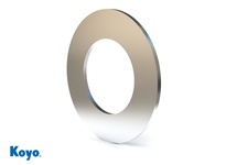
Koyo TRC-613 thrust needle roller bearing washer with 0.375" inner diameter, 0.812" outer diameter, and 0.095" width. This inch-series thrust washer is designed for use with needle roller cage assemblies in axial load applications such as automotive transmissions and industrial gearboxes.
MODEL TRC-613
$3.00 Each
Prices are subject to change
FREE SHIPPING ON ORDERS OVER $100
Select Quantity
Typically Ships in: 1 day
Returnable: See conditions
Bearing Design
Thrust Bearing Washer Only
I.D.
3/8 in
Matching Assembly
NTA613
O.D.
13/16 in
Oil Hole
w/o Oil Hole
Origin
Thrust Washer
Precision Ground
Yes
Self Aligning
No
Width
3/32 in
- Best used with our NTA FNT and AXK Needle Thrust Bearings for high axial load applications that require a thin cross section
- Thrust races are hardened flat and have a highly polished surface for the rollers to ride on
- Made from premium 1074 thru-hardened steel
How does the spherical self-alignment feature work, why does it matter, and what misalignment tolerance can it handle?
Spherical roller thrust bearings achieve self-alignment through their unique raceway geometry: the outer ring features a spherical (ball-like) cavity, and the barrel-shaped rollers sit in this spherical recess. How Self-Alignment Works: When the shaft is tilted slightly relative to the bearing housing (due to shaft deflection, misalignment during assembly, or differential thermal expansion), the spherical outer raceway permits the inner ring to tilt. The barrel-shaped rollers automatically re-center themselves on the tilted inner ring raceway, distributing the load evenly across all rolling elements. In contrast, cylindrical roller thrust bearings and ball thrust bearings have flat raceways; tilting the inner ring causes rolling elements to contact the raceway edge, concentrating load on one side and rapidly fatiguing the bearing. Misalignment Tolerance: Spherical roller thrust bearings typically tolerate angular misalignment of ±2–3 degrees depending on the specific bearing series and load condition. Why This Matters: Consider a vertical-shaft electric motor bearing the weight of its own rotor. The shaft experiences gravity load (radial), base misalignment from manufacturing tolerance, and thermal growth causing tilt. A cylindrical or ball thrust bearing would begin exhibiting edge-loaded raceway wear within weeks. A spherical roller thrust bearing (SKF 292, NSK 293 series) accommodates all three sources of tilt and operates trouble-free for years. This is why spherical roller thrust bearings dominate vertical-turbine-pump installations, marine propulsion systems, and any application where the bearing cannot be perfectly centered.
What are the three main types of thrust roller bearings, and how do their designs differ?
Thrust roller bearings are classified by roller geometry, each optimized for different axial load and speed requirements: Cylindrical Roller Thrust Bearings use flat, cylindrical rollers that contact the bearing raceways along a line (line contact). This geometry delivers the highest axial load capacity per unit size. Common SKF series include the 811 and 812 families. They cannot carry radial loads and excel in applications with pure axial loading at moderate speeds, such as screw jacks, gearbox shafts, and heavy-machinery thrust points. Tapered Roller Thrust Bearings employ conical rollers with angled raceways to handle both axial and moderate radial loads simultaneously. The tapered geometry distributes loads across multiple rolling elements and enables controlled preload adjustment during installation. They are valuable where rotating shafts experience both thrust and radial forces—for example, vertical-shaft pumps and automotive wheel hubs. Misalignment tolerance is typically ±1°. Spherical Roller Thrust Bearings contain two rows of barrel-shaped (spherical-profile) rollers seated in a spherical outer raceway, enabling self-alignment up to ±2–3 degrees. This geometry permits simultaneous high axial load capacity and radial load capacity (up to approximately 55% of the concurrent axial load). SKF's 292 and 293 series exemplify this design. They are the only thrust roller type that can safely absorb significant radial force—critical in vertical-shaft turbines, marine propeller shafts, and applications where shaft weight or radial reaction forces cannot be eliminated.
How do cylindrical and spherical thrust roller bearings differ in speed vs. load trade-offs, and which should I choose?
Cylindrical and spherical roller thrust bearings sit at opposite ends of the speed–load trade-off. Cylindrical rollers are shorter and lighter, producing lower friction and suiting higher speeds at light-to-moderate axial loads — screw drives, indexing tables, gearbox intermediate shafts. Spherical rollers carry substantially more axial load, tolerate simultaneous radial load and angular misalignment, but run slower. Choose cylindrical for pure axial load and speed, spherical where misalignment or shaft deflection is unavoidable.
How do I select a thrust roller bearing using load, speed, and service-life criteria per ISO 281?
Bearing selection follows a three-step framework: classify the load, check speed compatibility, then verify life expectancy. Step 1: Classify Your Load Profile For static loads (bearing at rest or <10 rpm), use static load ratings per ISO 76. Static safety factor = Cs₀ ÷ applied load; typically require ≥1.5 (or ≥2 for shock loads). For dynamic loads (continuous rotation), use dynamic load ratings per ISO 281. Step 2: Verify Speed Compatibility Calculate DN = bore diameter (mm) × speed (rpm). Example: A 50mm bore spherical roller thrust bearing (SKF 29310) at 500 rpm: DN = 50 × 500 = 25,000 — well below the ~70,000 limit for this bearing. Select grease lubrication. If DN exceeds the bearing's limit, oil lubrication or a different bearing type is required. Step 3: Calculate Service Life (ISO 281) For roller thrust bearings: L₁₀ = (Ca ÷ Pa)^(10/3) Where Ca = Basic Dynamic Axial Load Rating (kN from datasheet), Pa = Equivalent dynamic axial load (kN), L₁₀ = millions of revolutions at 90% reliability. L₁₀h = L₁₀ × 10⁶ ÷ (60 × speed in rpm) Example: SKF 29310 (Ca = 450 kN) carrying 120 kN at 1,000 rpm: - L₁₀ = (450 ÷ 120)^(10/3) = (3.75)^(10/3) ≈ 82 million revolutions - L₁₀h = (82 × 10⁶) ÷ (60 × 1,000) ≈ 1,367 hours For combined axial + radial loads on spherical roller thrust bearings: Pa = Fa + 1.2 × Fr (when Fr/Fa ≤ 0.55) Do not apply this formula to cylindrical or tapered thrust rollers—they cannot safely carry significant radial load.
Why do thrust roller bearings have higher load capacity than thrust ball bearings, and what is the engineering advantage?
The fundamental difference lies in contact geometry: roller bearings use line contact, while ball thrust bearings use point contact. Point Contact (Ball Thrust Bearings): In a ball thrust bearing, the spherical ball contacts the flat washer raceways at a single point. The contact patch is extremely small, and because the load is concentrated over this tiny area, the contact stress (Hertzian pressure) is very high. At high contact stress, subsurface fatigue initiates more readily. Line Contact (Roller Thrust Bearings): A cylindrical roller in a thrust bearing contacts the washer raceway along a line that extends across the full width of the roller. Because the contact is distributed over a line rather than a point, the contact pressure is substantially lower. A typical cylindrical roller thrust bearing of the same 50mm bore size carries 2–3 times the axial load of an equivalent ball thrust bearing. ISO 281 Bearing Life Formula: - For ball thrust bearings: L₁₀ = (Ca ÷ Pa)³, exponent p = 3 - For roller thrust bearings: L₁₀ = (Ca ÷ Pa)^(10/3), exponent p = 10/3 ≈ 3.33 The higher exponent for roller bearings reflects the gentler stress progression in line-contact geometry. In practical terms: if you exceed the load rating by 10%, a ball thrust bearing's life drops to ~75% of rated life (a 25% reduction). This superior load-carrying efficiency is why roller thrust bearings dominate heavy-machinery applications—cranes, mining equipment, vertical turbine shafts—where axial loads are sustained and high.
What are the main types of roller bearings and what is each used for?
Roller bearings are classified by roller geometry, with each type optimized for different load and speed conditions: Cylindrical Roller Bearings handle pure radial loads at the highest speeds among roller bearing types. They feature linear contact between cylindrical rollers and raceways. Common applications include machine tool spindles, wind turbine generators, printing presses, and rolling mills. Their low sliding friction enables them to operate at DN (bore diameter mm × speed rpm) values up to 2,000,000+. Tapered Roller Bearings are designed for combined radial and axial loads simultaneously, with the ability to absorb moment loads when used in pairs. They feature trapezoidal rollers with angled raceways. Typical applications include automotive wheel hubs, transmissions, pumps, and compressors. Spherical Roller Bearings excel in heavy machinery with shock loads and misalignment. They contain two rows of barrel-shaped rollers in a spherical outer raceway, enabling self-alignment up to ±3 degrees and simultaneous high radial and axial load capacity. Common applications include mining conveyors, crushers, cement mills, steel rolling mills, and wind turbine main shafts. Needle Roller Bearings provide maximum load capacity in minimum space through a distinctive high length-to-diameter ratio (typically 3-10:1 or higher). This slender, elongated roller geometry enables compact bearing designs where radial height must be minimized. Despite their compact profile, needle rollers deliver high stiffness and radial load capacity.
How do load ratings and bearing life relate to operating speed?
Roller bearing load ratings are specified under the ISO 281 standard. Understanding how load and speed interact helps predict bearing service life. Basic Dynamic Load Rating (ISO 281): The Basic Dynamic Load Rating (C) is a constant load that results in exactly one million revolutions before 90% of identical bearings fail from fatigue. This is the benchmark used by all bearing manufacturers (SKF, NSK, Timken, JTEKT). Fatigue Life Calculation: L₁₀ = (C ÷ P)^(10/3), where C = Basic Dynamic Load Rating, P = Actual dynamic equivalent load, L₁₀ = life in millions of revolutions at 90% reliability. Load-Life Relationship: If you reduce operating load to 50% of rated capacity, bearing life increases by a factor of 10×. If you double the load, bearing life reduces to 1/10 original life. Speed Rating and Operating Limits (DN = bore diameter mm × speed rpm): - DN <1,000,000: Grease-lubricated bearings perform optimally - DN 1,000,000-1,500,000: Transition zone; oil lubrication recommended - DN 1,500,000+: Oil lubrication required; risk of grease breakdown and bearing overheating Example: A cylindrical roller bearing with C = 100 kN carrying 20 kN load: L₁₀ = (100 ÷ 20)^(10/3) = 5^(10/3) ≈ 63 million revolutions. At 1,000 rpm this equals ~1,050 operating hours.
Which roller bearing type is best for heavy loads and shock impacts?
Spherical Roller Bearings are the first choice for heavy loads combined with shock impacts, vibration, and misalignment. Why Spherical Rollers Excel in Harsh Conditions: Their self-aligning design (±3 degree tolerance) accommodates shaft deflection and installation misalignment without premature wear. Two rows of barrel-shaped rollers distribute shock loads across multiple rolling elements, extending bearing life dramatically compared to single-row designs. The spherical raceway design enables simultaneous high radial load capacity and significant axial load capacity. Typical Applications: - Mining equipment and conveyors - Crushers, vibrating screens, and ore mills - Cement industry kiln systems - Steel rolling mill equipment - Paper machine dryer cylinders - Wind turbine main shafts - Marine propulsion systems Alternative for Combined Loads: If your application requires both heavy radial and axial loads but less misalignment tolerance, Tapered Roller Bearings (often used in matched pairs) provide superior precision and combined load handling. However, they require careful alignment and are less forgiving of shaft deflection than spherical rollers.
How do I properly mount a tapered roller bearing on a shaft?
Tapered roller bearing installation requires specific procedures to achieve proper preload and longevity. 1. Prepare the Shaft: Clean shaft surface thoroughly. Ensure bore diameter tolerance is within specification per bearing manufacturer guidance. 2. Determine Taper Ratio and Drive-Up Measurement: Tapered roller bearings are mounted on tapered shafts or tapered sleeves with specific reduction ratios: - 1:12 solid steel tapered shaft: 16× reduction - 1:12 tapered sleeve: 18× reduction - 1:30 solid steel tapered shaft: 39× reduction - 1:30 tapered sleeve: 42× reduction Example: 1:12 ratio with bearing bore 50mm requires approximately 50mm ÷ 16 = 3.1mm of axial movement to achieve the target preload. 3. Mount with Interference Fit: The inner ring must be seated with slight interference fit on the shaft taper. Do NOT install bearings loosely; negative clearance (preload) is essential for fatigue performance and stiffness. 4. Apply Lubrication Before Operation: For non-greased bearings, apply bearing grease into the housing grease sector via grease nipple before operation. Never leave a dry bearing installed. 5. Verify Installation: Measure the drive-up displacement along the shaft axis to confirm proper seating. Consult bearing specification sheet for target preload force.
When should I use a roller bearing instead of a ball bearing?
Roller bearings and ball bearings serve different load, speed, and precision combinations. Roller bearings have line contact between rolling elements and raceways, giving higher load capacity per unit volume than point-contact ball bearings, but that same line contact creates more sliding friction and limits speed. Choose roller bearings for heavy radial loads at low-to-moderate speeds, and ball bearings for high-speed rotation, lighter loads, combined radial and axial loads, or high precision.
What are dynamic and static load ratings, and why do they matter?
Static Load Rating (C₀) — The maximum load a stationary or slowly rotating bearing can support without permanent deformation of its rolling elements or raceways. Defined by ISO 76 as the load producing 0.01% permanent deformation of the rolling element diameter. Static load capacity is the limiting factor when a bearing operates at very low speeds or remains stationary under heavy loads. Dynamic Load Rating (C) — The constant load a bearing can endure for a specified number of revolutions (the L10 life, at which 90% of identical bearings are expected to survive). Dynamic load rating determines how long a bearing will last under rotating or oscillating motion. ISO 281 defines the L10 calculation using the formula: L10 = (C/P)^p, where C is dynamic load rating, P is equivalent dynamic load, and p is the life exponent (3 for ball bearings, 10/3 for roller bearings). Why They Matter — Static load rating determines if a bearing can handle peak loads without permanent damage (even if not rotating). Dynamic load rating determines operational life. For high-speed applications, dynamic rating is critical. For low-speed or stationary loads, static rating may be the limiting factor. Always verify both ratings against your application's load profile.
How should I maintain and lubricate bearings?
Lubrication Importance — Improper lubrication causes over 40% of bearing failures. Proper bearing lubrication prevents friction damage, dissipates heat, protects against corrosion, and acts as a barrier against contaminants (dust, moisture, debris). Lubrication Selection — Choose between grease and oil based on: - Grease: Suitable for low-to-medium speed, sealed bearings, and applications without continuous circulation. Easier to apply and retain. Common for motors, household appliances, and sealed units. - Oil Mist or Circulating Systems: Better for high-speed applications, high-temperature environments, and heavy-load machinery where heat dissipation is critical. Best Practices: 1. Map all lubrication points and create a maintenance schedule. 2. Use the correct lubricant type and viscosity grade specified by the bearing manufacturer. 3. Store lubricants in sealed, labeled containers away from moisture and contaminants. 4. Monitor bearing temperature and vibration; unusual heat or noise may indicate inadequate lubrication or bearing wear. 5. Replace bearings before reaching L10 life if contamination or lubrication failure is detected.
How do I choose the right type of bearing for my application?
Start with the load and how it’s applied. You need to know if you’re dealing with radial loads, axial loads, or a mix of both. Then look at speed, operating environment, and space constraints. For example, ball bearings are great for high speed and lighter loads, while roller bearings handle heavier loads but usually at lower speeds. If there’s contamination, moisture, or heat involved, you may need sealed bearings or specific materials. In most cases, the right choice comes down to matching load type, speed, and environment to the bearing design.
What is a bearing and what does it do?
A bearing is a mechanical component that enables smooth rotational or linear motion by reducing friction between moving parts. Bearings support loads and facilitate the transfer of forces between moving elements, preventing direct metal-to-metal contact that would cause wear and heat buildup. Rolling element bearings contain balls or rollers that rotate within races (raceways) to minimize friction. Common types include ball bearings (used for moderate loads and high speeds), roller bearings (used for heavy loads at medium speeds), and angular contact bearings (designed for combined radial and axial loads). Bearings are essential in industrial equipment including motors, pumps, compressors, gearboxes, turbines, and conveyor systems.
What bearing materials are available and which should I use?
Standard bearing materials include: - Chrome Steel — Premium bearing steel used by SKF, NSK, Timken, and most manufacturers. Offers excellent hardness, fatigue resistance, and durability in standard industrial applications. Most common for ball and roller bearings. - Stainless Steel — Provides corrosion resistance for applications in wet, humid, or chemically corrosive environments. Used in food processing, marine, and pharmaceutical equipment. - Ceramic Hybrid Bearings — Combine steel races with ceramic rolling elements. Offer reduced friction, lower heat generation, and higher temperature capability. Used in high-speed, high-precision applications and aerospace. - Polymeric Bearings — Utilize fluoropolymer composites with embedded graphite or PTFE. Provide low friction in high-speed applications where lubrication film breakdown would be problematic. Material selection depends on operating environment (temperature, moisture, chemical exposure), speed, load, and precision requirements. Standard chrome steel bearings suit most industrial MRO applications.
What is bearing life (L10) and how does it affect my equipment maintenance?
L10 Life Definition (ISO 281) — L10 is the basic rating life at which 90% of a large group of identical bearings are statistically expected to survive under constant load and speed. It is calculated in millions of revolutions using the formula: L10 = (C/P)^p, where C is the basic dynamic load rating, P is the equivalent dynamic bearing load, and p is the life exponent (3 for ball bearings). Converting L10 to Operating Hours — To express L10 life in hours: L10h = (L10 × 10^6) / (60 × n), where n is rotational speed in RPM. For example, a bearing with L10 = 1,000 million revolutions operating at 3,600 RPM has approximately L10h ≈ 4,630 hours. Modified Life (L10a) — Actual bearing life also depends on lubrication quality, contamination, speed, temperature, and bearing accuracy. ISO 281 defines a modified life factor (a₁ × aISO) that adjusts the theoretical L10 for these real-world conditions. High-quality lubrication and proper maintenance can extend bearing life significantly; poor lubrication or high contamination reduces it. Why It Matters for Maintenance — L10 life helps you schedule preventive maintenance, budget for bearing replacement, and select bearings adequate for your duty cycle.
How do I choose the right bearing for my application?
Bearing selection depends on five key factors: 1. Load Type and Direction — Determine whether your application has radial loads (perpendicular to shaft), axial loads (along the shaft), or combined loads. Deep groove ball bearings suit primarily radial loads; tapered roller bearings excel at combined loads; thrust bearings handle pure axial forces. 2. Rotational Speed — Ball bearings support higher speeds with lower friction. Roller bearings are better for medium-speed, heavy-load applications. Verify bearing speed ratings against your operating RPM. 3. Load Capacity — Select a bearing with adequate load capacity for your application. Basic dynamic load rating (C) and basic static load rating (C₀) determine how much load the bearing can safely carry. 4. Lubrication Requirements — Choose between grease and oil lubrication based on speed, temperature, and load. High-speed or high-temperature applications typically require oil circulation; lower-speed applications can use grease. 5. Precision and Rigidity — Evaluate your application's tolerance for runout deviation. High-precision applications require tighter tolerances and higher-grade bearings.

| Brand | Fasco |
| Model | D3325CW |

| Brand | Turck |
| Model | NI20U-S30-AN6X-H1141 |




| Brand | AMI Bearings |
| Model | MUCTPL205-14RFCEB |

